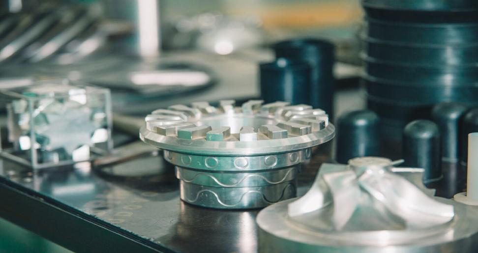
Die casting molds are the workhorses behind the high-precision, mass production of intricate metal parts. Designing an effective mold requires a well-defined process that considers various factors. Here’s a step-by-step breakdown to guide you through creating a successful die casting mold:
1. Part Analysis and Design Review:
Start with the Part: The journey begins with a thorough understanding of the final part you want to produce. Analyze its geometry, including dimensions, tolerances, wall thickness variations, and any internal features like holes or ribs.
Identify Potential Issues: Look for potential challenges in the part design that might impact the casting process. For instance, are there drastic changes in wall thickness that could lead to uneven cooling? Are there internal features that require complex core designs?
2. Mold Design and Development:
3D Modeling: Utilize CAD software to create a detailed 3D model of the die casting mold. This model should encompass all the mold components, including the die cavity, cores (if needed), runner system, cooling channels, and ejection system.
Parting Line Determination: Define the parting line, which is the imaginary line where the two halves of the mold open to allow part removal. Consider factors like part geometry and ease of mold operation when determining the parting line location.
3. Gating System Design:
The Gating System’s Role: The gating system of plastic injection molding China plays a crucial role in controlling the flow of molten metal into the mold cavity. It consists of the sprue (entry point), runner (channels), and gate (the final point where metal enters the cavity).
Optimizing Flow: Design the runner system to minimize pressure drops, turbulence, and premature solidification. Consider factors like runner size, shape, and gate location to ensure a smooth metal flow that fills the cavity uniformly.
4. Cooling System Design:
Rapid Cooling is Key: Rapid cooling of the casting is essential for achieving dimensional stability and preventing defects. Design a network of cooling channels throughout the mold, particularly near thicker sections of the part. Water or oil are commonly used as coolants circulating within these channels.
Balancing Cooling: Strive for balanced cooling to prevent uneven shrinkage and warpage in the cast part. The placement and size of cooling channels should be optimized to achieve a uniform cooling rate across the entire casting.
5. Ejection System Design:
Efficient Part Removal: The ejection system ensures the solidified casting is efficiently removed from the mold cavity after solidification. This typically involves ejector pins strategically placed to apply a balanced force on the part.
Ejection Mechanism Selection: Choose an appropriate ejection mechanism based on the part size and complexity. Hydraulic or mechanical actuation are common options for applying the necessary force for part removal.
6. Draft Angles and Venting:
Draft for Easy Removal: Draft angles are slight tapers incorporated on the walls of the mold cavity. They allow for easier part removal after solidification and prevent damage to the mold. Typical draft angles range from 1 to 3 degrees but may need adjustment for specific features.
Venting for Trapped Air: Entrapped air within the mold cavity can lead to surface porosity or other defects. Strategically placed vents are channels that allow trapped air to escape during the casting process.
7. Mold Material Selection:
Matching Material to Needs: The choice of mold material depends on factors like the metal being cast, production volume, and part complexity. Tool steel is the most common choice due to its excellent combination of strength, hardness, and thermal conductivity.
Considering Options: H-13 steel is a popular and affordable option for many applications. H-21 steel offers superior hot strength for high-volume production, while maraging steel provides exceptional dimensional stability for parts requiring tight tolerances.
8. Mold Simulation (Optional):
Virtual Analysis: Mold simulation software allows you to virtually analyze the filling process, heat transfer, and potential stress points within the mold design. This can be a valuable tool for identifying potential issues like unbalanced filling, hot spots, or inadequate venting before the mold is manufactured.
9. Collaboration and Manufacturing:
Working with Mold Makers: Collaborate with experienced mold makers throughout the design process. Their expertise can be invaluable in optimizing the design for manufacturability and ensuring the mold meets the required quality standards.
Mold Manufacturing: Once the final design is approved, the mold maker will use specialized techniques like CNC machining, spark erosion, and polishing to manufacture the mold components with high precision.
In Conclusion:
Designing a die casting mold is a meticulous process requiring careful consideration of various factors. By following this step-by-step guide, you can develop a mold that optimizes metal flow, minimizes casting defects, and ensures efficient production of high-quality parts. From analyzing the part geometry to selecting the appropriate mold material and collaborating with experienced mold makers, each step plays a crucial role in the success of the die casting mold. Additionally, utilizing mold simulation software can provide valuable insights for further refinement of the design. Ultimately, a well-designed die casting mold translates to a cost-effective and reliable production process for your desired metal parts.
Also Read:-
- The Future of Betting is Digital: Ladbrokes’ Vision Unveiled
- The Use of AI Technology in Monitoring Endangered Species
- The Psychology of Motivation: Strategies for Achieving Goals

